| Terminology | Commentary |
| Rated Capacity | Design value of the upper limit in the measuring range. |
Rated Load | Upper limit of load at which the transducer performs to the specifications. |
| Load exceeding the rated capacity.
Safe Overload Rating
Maximum overload which may not cause any permanent change to stated specifications, expressed in percentage of the rated capacity.
Ultimate Overload Rating
Maximum overload which can be applied without causing any structural damage, expressed in percentage of the rated capacity. |
| Rated Output | Value obtained by deducting the output under no load from the output under the rated capacity. Usually, it is expressed in mV/V, mA or equivalent strain.
Rated Output Voltage
Rated output expressed with the output voltage at the open end. It is expressed together with the excitation voltage.
Rated Output Current
Rated output expressed with the current flowing when connected to a prescribed load impedance. It is expressed together with the excitation voltage and load impedance
Rated Output Equivalent Strain
Rated output expressed with a value converted into strain, with the gage factor 2.00. |
| Sensitivity | Ratio of changing output to changing load. Usually, it is expressed in mV/V or x10-6 strain per 1-V excitation voltage. |
| Calibration Constant | Ratio of the rated load to the rated output. |
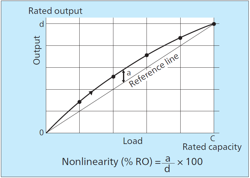
| Nonlinearity | Maximum deviation of output between the calibration curve in the increasing load cycle and the reference line (straight line drawn from the output under no load to the rated output under the rated capacity); expressed in percentage of the rated output.
|
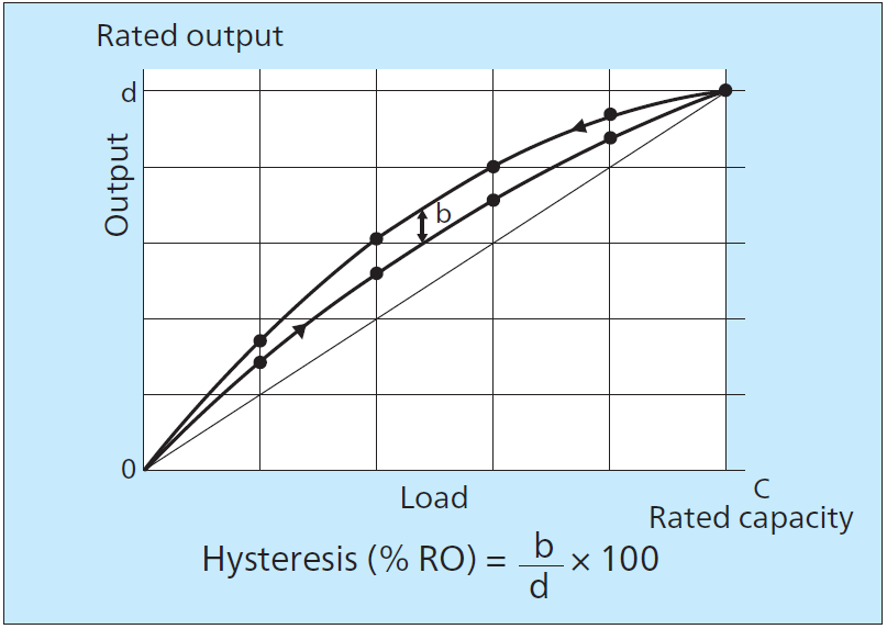
| Hysteresis | Difference of output between the calibration curve traced in the increasing load cycle and that in the decreasing load cycle. Usually, the calibration curve is reciprocated between the null load and the rated capacity and the maximum difference in outputs corresponding to the same load is defined as the hysteresis, expressed in percentage of the rated capacity. |
| Natural Frequency | Frequency due to free vibration of the transducer under no load. |
| Frequency Response Range | Frequency range in which the output can respond to the input at the same amplitude and phase within certain range of error when the input is steady-state sinusoidal. |
| Excitation Voltage | Voltage applied to the input terminal of transducer. |
| Recommended Excitation Voltage | Maximum excitation voltage with which the transducer can perform to the specifications. |
| Safe Excitation Voltage | Maximum excitation voltage with which the transducer may not perform to the specifications but when the recommended excitation voltage is recovered, the transducer performs to the specifications. |
| Input/Output Resistance | Resistance of input or output terminal. Use of the termis limited to the indication of the nominal resistance of an input or output terminal. Input Terminal Resistance Resistance between input terminals with output terminals open under no load. Output Terminal Resistance Resistance between output terminals with input terminals open under no load. |
| Temperature Effect on Zero Balance | Change of zero due to change of ambient temperature; expressed as a change of zero per 1°C in percentage of the rated output (xx% RO/°C). |
| Temperature Effect on Output | Change of gain due to change of ambient temperature, expressed as a change of zero per °C in percentage(xx%/°C). |
| Compensated Temperature Range | Temperature range which guarantees that the transducer performs to the specifications with regard to temperature effects on output and zero balance. |
| Safe Temperature Range | Temperature range in which the transducer may not perform to the specifications but does not receive any permanent change in the specifications |
| Repeatability | Maximum difference between output variables initiated by repeatedly applying the same load under the same conditions. Usually, it is measured using the rated load and expressed in percentage of the average rated output. |
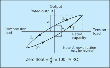
| Zero Balance | Output under no load with the transducer placed in the prescribed posture. Usually, it is expressed in mV/V, x10-6strain or percentage of the rated output. |
| Zero Stability | Degree at which the transducer keeps the zero under prescribed conditions. |
| Stability | Capability of the transducer to keep the characteristics for a comparatively long period. Unless noted, it is the capability to maintain the characteristics such as calibration factor and nonlinearity obtained at the initial calibration, under room conditions and for a prescribed period. If it is expressed by quantitatively numeric values, stability can be called as "degree of stability". |
| Interference | With a multiple component transducer, effects of the rated output applied to one component on outputs of other components are expressed in percentage of the rated output of each component |
| Recommended Tightening Torque | Tightening torque required to let the transducer perform to the specifications. |
| Resonance Frequency | Frequency of input mechanical vibration causing maximum response output of the transducer. |
| Cycling Life | Minimum number of repeated operations under the rated or prescribed load without exceeding allowable ranges of specified characteristics. |
| Degree of Protection | Degree of protection against invasion of a solid matter or water; expressed using IP rating stipulated in JIS C 0920 |
| Weight | Expressed in kg or g. If items other than the mainframe are included, the fact is noted. |
| Material | Material of the mainframe, bottom panel or cable outlet is expressed using the type code stipulated in JIS. Surface treatment such as plating or painting is also noted. |
| Cable | Cable to be connected to the transducer through the connector or straight cable to the internal circuit. Nominal cross section of conductor, number of conductors, material of shield or sheath, length and nominal outer diameter and condition of the tip are stated. |