
- หน้าแรก
- สินค้าของเรา
-
ข้อมูลทางเทคนิค
-
Strain gage
-
Strain Gage Basic Information
- What's a Strain Gage
- Types of Strain Gages
- Self-Temperature-Compensation Gages (SELCOM Gages)
- Major Properties of KYOWA Strain Gages
- Strain gage bonding installation procedure
- Strain Gage Wiring System
- Principles of Strain Gages
- How to Select Strain Gages
- Strain Gages with Pre-attached Lead-wire Cables
- Strain Measurement
-
Measurement Knowledge
- Misalignment Effect of Bonding Strain Gage
- Generating Calibration Value Based on Tip
- Resistance Change of Strain Gages
- Strain Gage Bonding Procedure
- Compensation formulas for strain gage
- Countermeasures against Failure in Initial Balance
- Influence of Insulation Resistance
- Temperature Effect on Lead Wire with 2-wire
- Compensation Methods of Temperature Effect
-
Strain Gage Basic Information
-
Transducers
- Transducers
- Basic information of strain gage type sensors
-
Measurement Knowledge
- Sensitivity Decrease due to Cable Extension
- Equation to Calculate Centrifugal Acceleration
- Connection to Calculate Average Output Voltage
- How to Obtain Proper Rated Capacity of Load Cell
- TEDS
- Advantages of Remote-Sensing Method
- Graphs to Obtain Power or Work
- Installation of Load Cell to Hopper or Tanks
- How to Obtain Accuracy of Load Cell-Based
- Measuring Instruments
- Videos for how to use KYOWA products
- Unit Conversion Table
- Glossary
- FAQ
-
Strain gage
- ดาวน์โหลด
- ข่าวสาร l กิจกรรม
- บทความ
- เกี่ยวกับเรา
- ติดต่อเรา
- ลงทะเบียน
Quarter-bridge System (1-gage System)
See the figure below. If a strain gage is bonded on a surface of a pillar which receives uniform load from one direction and the gage axis is aligned to the direction, stress σ is calculated by the following equation :
Stress (σ) = ε0 ・E
where, E : Young's modulus (See table "Mechanical Properties of Industrial Materials" at the left.)
ε0 : Indicated strain
And, the load W applied to the pillar is obtained by the following equation:
Load W = A・σ
where, A: Cross-sectional area of the pillar

Half-bridge System (2-gage System)
If another strain gage is bonded to the pillar at a right angle to the loading direction and 2 gages are connected to adjacent legs of the bridge, the surface stress σ on the pillar is expressed by the following equation:
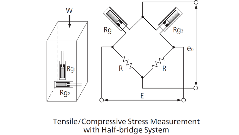

If 2 more strain gages are bonded to the opposite sides of the pillar to eliminate bending strain and full-bridge system is adopted, the surface stress σ is calculated by the following equation:
