
- หน้าแรก
- สินค้าของเรา
-
ข้อมูลทางเทคนิค
-
Strain gage
-
Strain Gage Basic Information
- What's a Strain Gage
- Types of Strain Gages
- Self-Temperature-Compensation Gages (SELCOM Gages)
- Major Properties of KYOWA Strain Gages
- Strain gage bonding installation procedure
- Strain Gage Wiring System
- Principles of Strain Gages
- How to Select Strain Gages
- Strain Gages with Pre-attached Lead-wire Cables
- Strain Measurement
-
Measurement Knowledge
- Misalignment Effect of Bonding Strain Gage
- Generating Calibration Value Based on Tip
- Resistance Change of Strain Gages
- Strain Gage Bonding Procedure
- Compensation formulas for strain gage
- Countermeasures against Failure in Initial Balance
- Influence of Insulation Resistance
- Temperature Effect on Lead Wire with 2-wire
- Compensation Methods of Temperature Effect
-
Strain Gage Basic Information
-
Transducers
- Transducers
- Basic information of strain gage type sensors
-
Measurement Knowledge
- Sensitivity Decrease due to Cable Extension
- Equation to Calculate Centrifugal Acceleration
- Connection to Calculate Average Output Voltage
- How to Obtain Proper Rated Capacity of Load Cell
- TEDS
- Advantages of Remote-Sensing Method
- Graphs to Obtain Power or Work
- Installation of Load Cell to Hopper or Tanks
- How to Obtain Accuracy of Load Cell-Based
- Measuring Instruments
- Videos for how to use KYOWA products
- Unit Conversion Table
- Glossary
- FAQ
-
Strain gage
- ดาวน์โหลด
- ข่าวสาร l กิจกรรม
- บทความ
- เกี่ยวกับเรา
- ติดต่อเรา
- ลงทะเบียน


ข้อมูลทางเทคนิค
Countermeasures against Failure in Initial Balance (Resistant Balance)
When bonding a strain gage to a curved surface or when using a semiconductor gage providing a wide resistance range, initial balance may not be taken occasionally. As an emergency countermeasure against such the case, there is a parallel resistance method described below.
Insert the following parallel resistance Rp into the bridge:
Rp = R・Rg / | R – Rg |
where,
Rg : Resistance of strain gage
R : Nominal resistance of bridge
The side of the bridge to which the parallel resistance is inserted is the opposite side of the strain gage if Rg is larger than R, meanwhile the adjacent side if Rg is smaller than R.
Insert the following parallel resistance Rp into the bridge:
Rp = R・Rg / | R – Rg |
where,
Rg : Resistance of strain gage
R : Nominal resistance of bridge
The side of the bridge to which the parallel resistance is inserted is the opposite side of the strain gage if Rg is larger than R, meanwhile the adjacent side if Rg is smaller than R.
In the case of R=120Ω

Precaution: When using resistors of E24 system
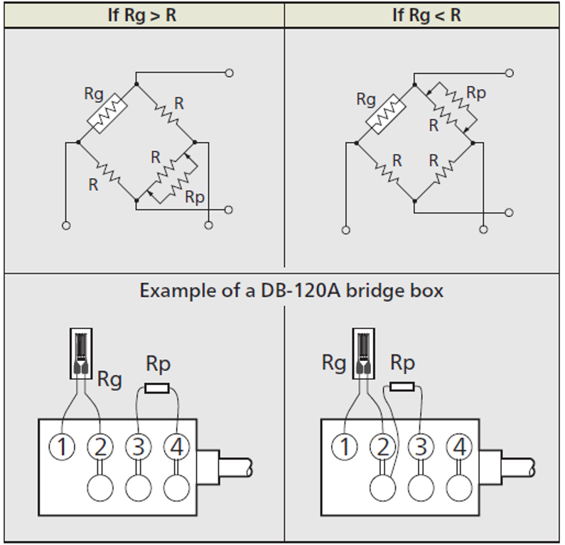
Precaution : Avoid inserting Rp to the side where the strain gage is connected. Such connection adversely affects the sensitivity.
เราใช้คุกกี้เพื่อปรับปรุงไซต์ของเราและประสบการณ์ของคุณ อ่านเพิ่มเติมได้ที่ นโยบายความเป็นส่วนตัว